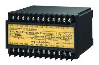
Power transducer category: isolated measurement signals for PLC, DCS and panel instruments
A power transducer converts measured electrical quantities — voltage, current, active power, reactive power, apparent power, power factor and frequency — into standard analog signals that a PLC, DCS, SCADA system or panel meter can read directly. LOGGON TECH supplies two families for this duty: the programmable PRO M31, which uses microprocessor and digital signal technology to measure and output several quantities from one unit, and the traditional PRO series of single-function current and voltage transducers with galvanic isolation. Isolation for the PRO M31 is confirmed against its datasheet. The PRO M31 documentation states manufacture under an ISO 9001:2000 quality system. This page sets out the models, the selection criteria and the integration points an electrical engineer needs when specifying a power transducer for a switchgear panel, a machine control cabinet or a plant monitoring system.
Overview: what a power transducer does and where it is installed
In most industrial installations the protection and metering devices on the primary side are not the devices that the control system talks to. The transducer sits between them. It takes a voltage or current input from the circuit — often via instrument transformers — and produces a proportional DC current or voltage signal on the secondary side. On the traditional PRO family that signal is galvanically isolated: the isolation separates the control electronics from the measured circuit, limits fault energy reaching the PLC input card, and lets a standard 4–20 mA or 0–10 V input module be used regardless of the primary voltage or current level.
Typical installation points include low-voltage distribution panels feeding a PLC or DCS, motor control centres where load current is logged, generator and transformer panels where active and reactive power are trended, and building or process energy monitoring cabinets. In these panels the transducer output usually goes to one of three destinations: an analog input card on a PLC or DCS, a SCADA front end via the controller, or a local panel instrument for operator display. The related current transducer function — converting AC current alone into a proportional isolated DC signal — remains common in panels where only load current is needed and a full multi-parameter unit is not justified.
Models in this range
Programmable power transducer PRO M31
The PRO M31 is the multi-parameter model. It uses a microprocessor and digital signal technology to measure U, I, P, Q, S, power factor and frequency in real time. Input ranges are wide: voltage 0–693 V and current 1–5 A. Three analog outputs are programmable, each configurable as voltage bipolar −10 to 0 to +10 V, voltage unipolar 1–10 V, current bipolar −20 to 0 to +20 mA or current unipolar 1–20 mA. An RS-232 interface is provided. The unit is documented against IEC688, IEC1010, IEC529, IEC68-2, IEC61000-4 and IEC61010, and its documentation states manufacture under the ISO 9001:2000 system.
Traditional PRO series: current transducers I31, I32, I33
The I31 is an AC current transducer that converts AC current into a proportional, isolated DC current or voltage signal. The I32 is a two-in-one unit that integrates two I31 transducers in one housing, providing three-phase current input with three isolated outputs. The I33 is the three-in-one version. All provide galvanic isolation between input and output; transformer isolation is documented for the voltage members.
Traditional PRO series: voltage transducers U31, U32, U33
The U31 is an AC voltage transducer with the same transformer-isolation principle. The U32 is the two-in-one version and the U33 the three-in-one version, matching the packaging logic of the current range.
How to select
- Parameters required. If the control system needs power, power factor or frequency as well as current and voltage, the PRO M31 covers all of them in one unit with three programmable outputs. If only one or two quantities are needed, a traditional I31/U31 single-function unit is sufficient. For three-phase circuits where each phase must be measured separately, the PRO I32 is the documented consolidated option (three-phase current input, three isolated outputs); other multi-channel builds (U32/I33/U33) require model-specific drawings to confirm their terminal mapping.
- Input level. Confirm the actual circuit voltage and current at the transducer terminals, including any instrument transformer ratio. The PRO M31 accepts 0–693 V and 1–5 A directly; where the circuit exceeds these values, use external voltage or current transformers and size the transducer input to the secondary values.
- Output type. Match the output to the receiving device. Most PLC analog input cards accept 4–20 mA or 0–10 V; bipolar outputs are used where the measured quantity can reverse sign, such as power in a circuit that can export or import. The PRO M31's programmable outputs allow the same unit to be stocked against several panel designs.
- Isolation and environment. Check the isolation requirement between input and output and the panel ambient conditions. The PRO M31 is documented against the IEC standards listed above; apply the relevant IEC61000-4 immunity tests and IEC61010 safety requirements to the panel design as a whole, not only to the transducer.
Integration and communication
Wiring practice is straightforward: input on the measuring side, output on the control side, with shielded cable for analog runs and the shield grounded at one end. For the PRO M31, an RS-232 interface is provided alongside the three analog outputs; the interface's role and the configuration method are confirmed against the current documentation. On traditional units, verify the burden of the receiving analog input against the transducer output rating, and scale the PLC or SCADA engineering units to the selected output range — for example, 4–20 mA mapped to 0–100 % of the nominal input.
FAQ
Can one PRO M31 replace several single-function transducers?
Yes. It measures U, I, P, Q, S, power factor and frequency in real time and provides three programmable analog outputs, so up to three quantities can be sent as separate signals from one unit.
What output ranges are available on the PRO M31?
Each of the three outputs can be set to voltage bipolar −10 to 0 to +10 V, voltage unipolar 1–10 V, current bipolar −20 to 0 to +20 mA, or current unipolar 1–20 mA.
What is the difference between the I31, I32 and I33?
The I31 converts one AC current input into a proportional, isolated DC current or voltage signal. The I32 integrates two I31 units in one housing and accepts three-phase current input with three isolated outputs. The I33 is the three-in-one version.
How do I know the transducer suits my panel environment?
Check the documented standards for the model against your panel requirements. The PRO M31 is documented against IEC688, IEC1010, IEC529, IEC68-2, IEC61000-4 and IEC61010, and its documentation states manufacture under ISO 9001:2000.
For a panel buyer, the practical split is simple: choose the PRO M31 when several parameters must be measured with programmable outputs (configuration arrangements per the current model documentation), and choose the I31/I32/I33 or U31/U32/U33 when a single quantity per phase is enough. Confirm input levels, output type and isolation against the receiving equipment before ordering, and keep the transducer documentation with the panel drawings so that scaling and configuration can be verified during commissioning.