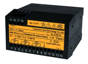
Voltage transducers and current transducers for panel and OEM integration
In general category terms, a voltage transducer converts an AC or DC voltage into a proportional, isolated DC signal that a PLC, meter, or SCADA input can read directly; the traditional PRO voltage and current models listed on this page are documented for AC inputs. The same conversion principle applies to current: an ac current transducer scales a line or CT-secondary current into a signal the control system can handle. The PRO series covers both functions in single-channel and multi-channel housings, so a panel designer can select one electrical transducer family for current and voltage measurement across a machine or switchgear lineup. The voltage members use transformer isolation; the current members provide galvanic isolation between the measured circuit and the output.
Category overview: where isolated transducers are used
Isolation is the primary reason these devices exist. A measuring circuit connected directly to a PLC input creates a galvanic path between the power circuit and the control electronics. That path carries three risks: fault voltage reaching the low-voltage side, ground loops between separately earthed panels, and surge energy coupled through the signal cable. Isolation breaks the path while preserving the measurement, rather than relying on direct-coupled dividers or shunts; transformer isolation is the documented construction for the voltage members of the PRO range.
Typical installation points include motor control centres, distribution panels, gensets, HVAC plant rooms, water treatment cabinets, and OEM machinery where a controller needs a proportional representation of current or voltage. In these locations the transducer output feeds analog inputs on a PLC, a data logger, or a panel meter. The output is a proportional DC current or voltage signal, which allows cable runs of tens of metres without the loading errors that a raw voltage divider would suffer.
For current measurement, the conventional interface is a current transformer with a 1 A or 5 A secondary. The transducer is specified on that secondary current, not on the primary conductor, so the same unit can serve different primary ratings by changing the CT ratio. Voltage inputs are taken either directly, where the system voltage suits the device, or through a voltage transformer on medium-voltage systems. In both cases the transducer's job is to present a linear, isolated, low-level signal that the control system can scale back to engineering units.
Models in this range
The PRO traditional series is organised by channel count and by measured quantity. Each model provides an isolated output stage.
- PRO I31 — AC current transducer, single channel. Isolated conversion of AC current into a proportional DC current or voltage output. One input, one output, one housing.
- PRO I32 — two-in-one current build. Two I31 circuits integrated in one housing, with three-phase current input and three isolated outputs. This suits a three-phase feeder where all three phases are monitored from a single module width.
- PRO I33 — three-in-one current build. Three I31 circuits in one housing; confirm its input and output mapping from the datasheet.
- PRO U31 — AC voltage transducer, single channel. Isolated conversion of AC voltage into a proportional DC output.
- PRO U32 — two-in-one voltage build. Two voltage channels in one housing with isolated outputs.
- PRO U33 — three-in-one voltage build. Three voltage channels in one housing with isolated outputs.
For designs that need programmable outputs, the alternative is the PRO M31. It is the digital option in the range and provides three programmable analog outputs across the documented conventions and ranges. For traditional PRO units, confirm the output range and any configuration options for the exact model before ordering.
How to select
Selection follows four steps, in this order.
- Measured quantity and channel count. Choose the U series for voltage, the I series for current. Use a single-channel build (31) for one measurement point. For multi-channel builds, the captured description is model-specific — the PRO I32 integrates two I31 circuits with three-phase current input and three isolated outputs; confirm the channel mapping of any (32)/(33) build from its datasheet.
- Input scaling. For current, decide on the CT ratio and its 1 A or 5 A secondary, then confirm the transducer is specified for that secondary. For voltage, confirm whether the input is taken directly or from a voltage transformer.
- Output convention. Decide whether the receiving device expects a current loop or a voltage signal. A power transducer 4-20ma output convention is common where the PLC input card is current-sourced and where the signal must survive long cable runs; voltage outputs suit short runs and legacy input cards. Traditional PRO units are ordered to match the required convention (confirm the output range and any configuration options for the exact model), while the M31 provides programmable outputs across its documented ranges (configuration method per the current documentation).
- Isolation and environment. Confirm the isolation requirement between the measured circuit and the control side, and check the panel ambient temperature and the mechanical fit (confirm the mounting format for the model). Allow adequate ventilation in dense cabinets.
Integration and communication
Wiring follows the model's wiring diagram: the measured circuit connects to the input side and the control system to the output side; confirm the auxiliary supply arrangement against that diagram. Keep input and output cabling physically separated inside the panel, and earth the module according to the panel's earthing scheme. On the traditional PRO units the output is isolated, so the receiving analog input does not need to share a reference with the measured circuit; for the PRO M31, check the isolation and reference arrangements against its datasheet.
When the output feeds a PLC analog card, set the card's input range to match the transducer's output convention and document the scaling in the panel schedule so that the value in engineering units can be recovered. For the PRO M31, record the programmed output configuration and keep it with the panel documentation, since its outputs are programmable across the documented ranges (configuration arrangements per the current documentation).
FAQ
Why does isolation matter in a transducer?
It separates the measured power circuit from the control electronics, limiting fault voltage transfer, breaking ground loops between panels, and reducing surge energy reaching the PLC input.
Should I choose a single-channel or multi-channel build?
Use a single-channel unit for one measurement point. For a three-phase feeder, the PRO I32 is the documented consolidated option (two I31 circuits, three-phase current input, three isolated outputs); confirm other multi-channel builds against their datasheets.
Can I use the same transducer with different CT ratios?
The transducer is specified on the CT secondary, conventionally 1 A or 5 A. Changing the primary rating is done by changing the CT, not the transducer.
When should I use the programmable PRO M31?
When the output range or convention must be adjustable, or when one module should cover several scaling requirements instead of a set of fixed-range units.
For panel builders and plant buyers, the practical decision is to match channel count to the feeder, match input scaling to the CT or VT, and match the output to the receiving analog card. The PRO series covers those combinations with galvanically isolated current and voltage transducers, and the PRO M31 provides the programmable path in the range.