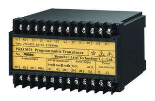
PRO M31 programmable transducer
The PRO M31 programmable transducer is a microprocessor-based instrument for real-time measurement and conversion of electrical quantities in industrial power systems. It samples voltage and current inputs continuously, processes the signals digitally, and provides three programmable analog outputs alongside an RS-232 interface (the interface's role in a given installation is confirmed against the current documentation). All measurement channels are processed by the unit's microprocessor-based digital signal chain. The programmable transducer is intended for installation in switchgear panels, machine control cabinets and energy monitoring points where local analog signals are required alongside the documented interface.
What it measures / does
The PRO M31 measures in real time the following quantities:
- Voltage (U)
- Current (I)
- Active power (P)
- Reactive power (Q)
- Apparent power (S)
- Power factor (PF)
- Frequency (F)
Digital signal processing is carried out by the internal microprocessor. An RS-232 interface is provided; its role in a given installation is confirmed against the current documentation. In parallel, three analog outputs deliver proportional signals for panel meters, PLC analog cards, recorders or SCADA remote terminal units. Each of the three outputs is programmable as voltage or current, bipolar or unipolar, across the documented output ranges. The voltage input range is 0~693 V and the current input range is 1~5 A, which covers low-voltage distribution levels directly and allows higher currents to be handled with external current transformers. For engineering guidance only, when a current transformer is used the primary current is obtained by multiplying the measured secondary current by the CT ratio; the analog output scaling should be configured accordingly.
Key features
- Microprocessor-based design with digital signal processing of all measured quantities
- Real-time measurement of U, I, P, Q, S, PF and F from a single instrument
- RS-232 interface (role per current documentation)
- Three programmable analog outputs, each configurable as voltage or current
- Voltage output modes: bipolar -10~0~+10 V or unipolar 1~10 V
- Current output modes: bipolar -20~0~20 mA or unipolar 1~20 mA
- Voltage input range 0~693 V; current input range 1~5 A
- Documented against IEC688, IEC1010, IEC529, IEC68-2, IEC61000-4 and IEC61010
- Quality system stated in the manufacturer's documentation: ISO 9001:2000
The bipolar output modes are useful where the sign of a quantity carries information, for example power direction in import/export metering or reactive power in capacitive versus inductive operation. Unipolar modes suit standard PLC and meter inputs that accept only positive signals. The three analog outputs are programmable across the documented output ranges; confirm the configuration arrangement for the exact unit with the export department, and re-range the connected device to match the selected mode.
Specifications
| Model | PRO M31 |
|---|---|
| Product type | Programmable transducer, microprocessor-based with digital signal processing |
| Measured quantities (real time) | U, I, P, Q, S, PF, F |
| Interface | RS-232 |
| Analog outputs | Three programmable outputs |
| Voltage output modes | Bipolar -10~0~+10 V; unipolar 1~10 V |
| Current output modes | Bipolar -20~0~20 mA; unipolar 1~20 mA |
| Voltage input range | 0~693 V |
| Current input range | 1~5 A |
| Standards in documentation | IEC688, IEC1010, IEC529, IEC68-2, IEC61000-4, IEC61010 |
| Quality system | ISO 9001:2000 (per manufacturer documentation) |
Options and configuration
Configuration of the PRO M31 centres on the three analog outputs. Each output is assigned to a measured quantity (for example U, I or P) and set to one of the four output modes: bipolar voltage -10~0~+10 V, unipolar voltage 1~10 V, bipolar current -20~0~20 mA or unipolar current 1~20 mA. When planning the configuration, check the input impedance of the receiving device against the selected mode; current loops are preferable where cable runs are long or where induced noise on voltage signals is a concern. The scaling of each output should be chosen so that the normal operating range of the measured quantity uses most of the output span, which improves resolution at the receiving end. The RS-232 interface should be planned together with the analog wiring during panel design; its role is confirmed against the current documentation. Input wiring must respect the stated ranges of 0~693 V and 1~5 A; where system current exceeds the input range, a current transformer is required. Selection notes and wiring details are given in the product documentation.
Applications
The PRO M31 is suited to low-voltage distribution monitoring in industrial plants, where a single unit provides analog signals to a PLC or recorder alongside its RS-232 interface (whose role is confirmed against the current documentation). Typical uses include feeder and branch-circuit monitoring in switchgear panels, energy and power factor monitoring at machine level, retrofits where existing panel meters accept 4~20 mA-type or 0~10 V-type signals, and test benches that need real-time values of P, Q, S and PF. Because power direction can be represented by the bipolar output modes, the unit can also be applied at coupling points where import and export must be distinguished. The documentation set referencing IEC61000-4 (immunity) and IEC61010 (safety) supports specification into industrial electrical panels; the responsible engineer should still verify compatibility with the specific installation requirements. For guidance on commissioning and on matching the analog outputs to existing equipment, contact the manufacturer.
FAQ
How many analog outputs does the PRO M31 provide, and can they be configured independently?
The PRO M31 has three programmable analog outputs. Each output can be set as a voltage or current output, in bipolar or unipolar mode, covering -10~0~+10 V, 1~10 V, -20~0~20 mA and 1~20 mA. The outputs are intended for connecting panel meters, PLC analog inputs or recorders alongside the RS-232 interface.
What are the input ranges, and what is needed above them?
The voltage input range is 0~693 V and the current input range is 1~5 A. For systems with higher currents, an external current transformer is used and the measured secondary current is multiplied by the CT ratio; output scaling should be set to match. Voltage connections must stay within the stated range.
Which standards are referenced in the documentation?
The documentation references IEC688, IEC1010, IEC529, IEC68-2, IEC61000-4 and IEC61010. The manufacturer's documentation states that the product is manufactured under an ISO 9001:2000 quality system. These references describe the documentation and quality framework; engineers should confirm suitability for their specific installation.
What does the RS-232 interface do?
The unit measures U, I, P, Q, S, PF and F in real time and provides an RS-232 interface. The interface's role in a given installation is confirmed against the current documentation; the three programmable analog outputs feed conventional instruments in parallel.
Detailed wiring diagrams, output configuration notes and the full specification are provided in the product datasheet. To request the datasheet for the PRO M31 programmable transducer, or to discuss configuration for a specific panel, please use the contact page on this site.