Wireless Temperature & Humidity Monitoring System for Electrical Rooms and Motor Terminals
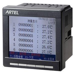
A temperature and humidity monitoring system is used where conventional wired sensors are difficult to route, difficult to maintain, or create a safety risk in the measured compartment. LOGGON TECH supplies wireless temperature and humidity monitoring equipment for switchgear contacts, busbars, cable joints, and explosion-proof motor terminal boxes. The range covers temperature probes mounted by alloy strap, tie strap or screw fixing (per model), a humidity probe, display terminals (the 1M1 documents Modbus-RTU output; each terminal's protocol is confirmed per project), wireless repeater units, and enclosure heaters. Probes transmit over RF links to the terminals; the LOGGON-1Z1/1Z2 repeaters operate at 470 MHz. Display terminals present the readings locally — the 1MH is a 7-inch touch terminal handling up to 240 channels — and pass data to a PLC or DCS over RS-485; the 1MH also provides an RJ-45 interface whose function is confirmed per project. Short-term variation curve display and alarm relay outputs are documented on the ARZ-1 display terminal.
What it does
Each wireless temperature and humidity monitoring point consists of a sensor probe and a receiver. The probe measures the surface or ambient value, transmits it over the RF link, and the terminal or collector presents the value; on the ARZ-1 system, the terminal also logs variation curves and switches an alarm relay when a set threshold is crossed. Because no signal cable runs from the probe to the terminal, the system suits measurement points inside sealed enclosures and on moving or hard-to-reach parts. Power arrangements differ by probe: the 1T3 is CT-powered from the conductor it monitors, the 1T5 is battery powered, and the 1T7 runs from 12 VDC or solar — confirm the arrangement for each probe when specifying.
Selection is governed by three parameters: the temperature range and accuracy required at the measurement point, the distance and obstructions between probe and receiver, and the number of channels the terminal must handle. The RF range figures below are quoted for unobstructed line-of-sight; metal partitions, closed cabinet doors, and cable trays reduce the achievable distance, so a site survey before installation is recommended.
Models and key data
LOGGON-100 temperature and humidity monitoring system
The LOGGON-100 system pairs three temperature probes and one humidity probe with display terminals, wireless repeaters, and heaters. Note that the humidity range and accuracy fields captured for this probe are withheld pending manufacturer confirmation; the figures published here are its response time and typical power consumption.
| Probe | LOGGON-1T3 |
|---|---|
| Temperature range | -20 to 125 °C |
| Accuracy | ±0.5 °C |
| Wireless range | 30 m, unobstructed |
| Power | CT-powered, ≥5 A |
| Mounting | Alloy strap |
| Probe | LOGGON-1T5 |
|---|---|
| Temperature range | -20 to 125 °C |
| Accuracy | ±0.5 °C |
| Wireless range | 100 m, unobstructed |
| Power | Lithium battery |
| Mounting | Tie-strap |
| Probe | LOGGON-1T7 |
|---|---|
| Temperature range | -20 to 125 °C |
| Accuracy | ±0.5 °C |
| Channels | 6 or 12, selectable |
| Wireless range | 100 m, unobstructed |
| Power | 12 VDC or solar |
| Mounting | Screw fixing |
| Humidity probe | LOGGON-1S1 |
|---|---|
| Response time | ≤ 4 s |
| Typical power consumption | 30 µW |
| Display terminal | LOGGON-1M1 |
|---|---|
| Channel management | 15 or 108 temperature channels |
| Wireless range | 100 m, unobstructed |
| Interfaces | 1x RS-485 + 1x RF |
| Protocol | Modbus-RTU |
| Supply | 85–265 VAC/DC |
| Display terminal | LOGGON-1MH |
|---|---|
| Display | 7-inch colour touchscreen |
| Channel capacity | Up to 240 channels |
| Interfaces | RS-232/RS-485 and RJ-45 |
| Wireless repeater | LOGGON-1Z1 / 1Z2 |
|---|---|
| Frequency | 470 MHz |
| Wireless range | 100 m, unobstructed |
| Interfaces | RS-485 + RF |
| Protocol | Modbus-RTU |
| Heater | LOGGON-1J |
|---|---|
| Supply | AC 220 V |
| Power options | 50 / 100 / 150 / 200 W |
LOGGON-7 system for explosion-proof motor terminal boxes
The 7 series uses carrier communication and is described by the manufacturer as a patented product that solves safe temperature and humidity measurement inside motor terminal boxes. It measures the box interior directly, so condensation and connection overheating are detected before they develop into insulation faults.
| Sensor | LOGGON-7A |
|---|---|
| Channels | 4 temperature + 1 humidity |
| Supply | 70–528 VAC |
| Temperature range / accuracy | -40 to +125 °C / ±1 °C |
| Humidity range / accuracy | 0–99.9 %RH / ±5 %RH |
| Data collector | LOGGON-7B |
|---|---|
| Sensor capacity | Up to 128 sensors |
| Supply | 70–528 VAC / 24 VDC |
| Interface | 1x RS-485 Modbus |
| Mounting | 35 mm DIN rail |
| Touch unit | LOGGON-HMI |
|---|---|
| Display | 7-inch touchscreen |
| Supply | 24 VDC |
| Interface | RS-485 Modbus-RTU |
| Mounting | Panel |
How it fits together / architecture
The architecture has four layers. Probes (LOGGON-1T3/1T5/1T7 and the LOGGON-1S1 humidity probe) sit at the measurement point and transmit wirelessly; the LOGGON-7A sensor belongs to the LOGGON-7 system, which uses carrier communication inside the motor terminal box. Receivers and collectors (LOGGON-1M1, LOGGON-1MH, LOGGON-7B) aggregate the channels. Wireless repeaters (LOGGON-1Z1/1Z2) extend the radio link where distance or building structure blocks a direct path. The documented supervisory connection is the 1M1 collector's RS-485 Modbus-RTU link to a PLC, SCADA, or DCS; the supervisory interfaces of the other collectors, including the 1MH terminal's RJ-45 interface, are confirmed per project.
- For a single switchgear room: 1T5 or 1T3 probes, one 1M1 terminal (15 channels), one 1Z1 repeater unit, and optional 1J heaters on the anti-condensation circuit.
- For a long busbar run or multiple rooms: 1T7 probes at 6 or 12 channels each, with 1MH terminals up to 240 channels.
- For a motor terminal box: 7A sensors inside the box, 7B collectors on DIN rail (up to 128 sensors each), and an HMI unit on the panel door.
Keep RF paths clear of continuous metal: mount probes so the antenna side faces the receiver, and keep the receiver outside closed metal enclosures where possible. Address each Modbus node before commissioning and record the channel map against the physical asset list.
Applications
- LV and MV switchgear: busbar and contact temperature, plus room humidity for condensation control.
- Explosion-proof motor terminal boxes: interior temperature and humidity via the 7 series.
- Cable joints and cable trenches: strap-mounted 1T3 probes on joints, humidity probes in the trench.
- Transformer and capacitor rooms: ambient temperature and humidity monitoring with alarm thresholds at the collector.
- Control and battery rooms: 1MH terminal (RJ-45 interface as published; its function in the installation is confirmed per project).
FAQ
How are the probes fitted and powered?
The CT-powered 1T3 mounts with an alloy strap and draws its power from CT induction (conductor current of at least 5 A); the battery-powered 1T5 uses a tie strap; the 1T7 is screw-fixed and runs from 12 VDC or solar. Whether any fitting work proceeds on live equipment is decided by the site's electrical safety and permit-to-work rules, not by the instrument.
How far can a probe transmit?
The 1T3 is rated 30 m unobstructed; the 1T5, 1T7, 1M1, and 1Z1/1Z2 are rated 100 m unobstructed. Closed metal doors and partitions reduce this, so verify at the site.
What interface does the terminal provide to the plant control system?
The 1M1 provides RS-485 with Modbus-RTU. The 1MH adds RS-232/RS-485 and RJ-45. The 7B collector provides RS-485 Modbus and the HMI unit RS-485 Modbus-RTU.
Does the humidity probe state a measuring range?
The published data for the LOGGON-1S1 gives response time ≤ 4 s and typical power consumption 30 µW. Confirm the 1S1 probe's humidity specification with the export department when the measurement point is specified; the 7A sensor is specified at 0–99.9 %RH with ±5 %RH accuracy.
For channel counts, probe selection, and wiring diagrams against a specific panel layout, send the single-line diagram and the number of measurement points to the LOGGON TECH contact page. The engineering team will confirm the terminal model, relay configuration, and Modbus register map before order.